Note page converted from archived team wiki page.
Project Objective
Modify the Donkey Car framework and physical car to autonomously deliver personalized mail to multiple different destinations based on number. Ideally, the Donkey Car model will be trained to do autonomous laps while hugging the right side of the road. Upon recognizing a mailbox number using OpenCV, the car will stop, queue the right package to be delivered, push the package off the side of the vehicle and continue on to the next delivery.
- Must have:
- Deliver personalized mail to or directly in front of all destinations. Personalized means that the address (in this case number) determines what mail is delivered.
- Train the car to do laps in autonomous mode and then deliver mail when near a driveway by using its mechanical on board systems
- Nice to have
- User controls where the mail gets delivered. Assigns numbers/symbols to individual mail on top of the car. In one trial, the user may assign the number 3 to package 2 and in another trial they can assign number 3 to package 4, etc.
- Train the car to hug the right side of the road in autonomous mode
- Car can recognize and associate QR codes with correct package. Essentially using QR codes instead of numbers.
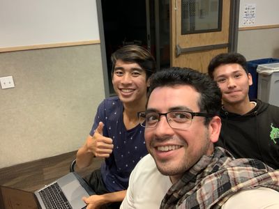
The Team
(from left to right)
- Andrew Ma, MAE
- Bijan Ardalan, MAE
- Lucas Hwang, ECE
Mechanical Design
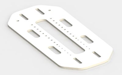
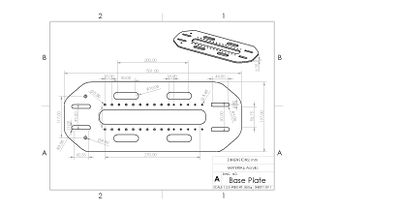
Acrylic Mounting Plate
Our mounting plate was designed very early on in the design process so our specific requirements were largely unknown at the time. The acrylic piece was designed to allow standard size motors to be mounted in the center and fed down through the middle gap of the baseplate. It was also designed with holes for a couple different screw sizes for mounting different components onto it. thin slots were designed in the front and back for zip ties and larger slots were put on the sides for cable management. We laser-cut the plate out of 1/4th inch acrylic since we had an idea that the plate would have to be pretty stiff to hold the entire mechanical package delivery system.
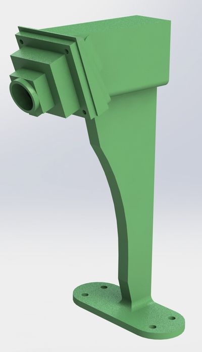
Camera Mounting
We originally angled our camera down 60 degrees from horizontal in order to capture a large image of the ground and track lines. However, in order to capture the numbers for our package delivery on the side of the road, this angle was decreased to 30 degrees to capture more of the horizon. The camera was held 195 mm above the acrylic base plate. We also designed an optional +-10 degree extender piece just in case we needed to fine-tune the camera angle further. This piece can be seen clearly in the exploded view below.

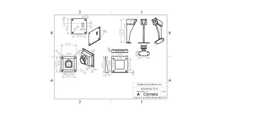
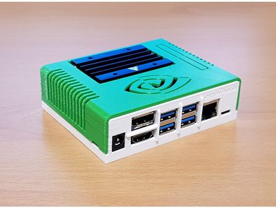
Jetson Case
To house our Jetson Nano, we 3D printed a case taken off of Thingiverse at https://www.thingiverse.com/thing:3518410
Mail Delivery Mechanism
We used a double rack and pinion design and two linear sliders for the moving components of the build. The racks were rigidly attached to the linear sliders and the motors were rigidly attached to the base plate to enable linear motion and two degrees of freedom. The package rack and pinion selects a package to deliver and then the push rack and pinion knocks the package off the car near the sign. We designed the rack and pinions in SolidWorks and then laser cut them out of acrylic. Standoffs were designed to accommodate the different heights necessary. The packages are also held down in case of a bumpy ride by Velcro.

Choosing The Motors
Our design requirements were based on the need to precisely choose a package to deliver. We chose to use servo motors instead of DC motors because they have internal control systems which saves us from having to design and implement external sensors and a control system. Originally we used the servo motors already in the lockers, however we realized that they were "position" servos that had a limited degree of rotation. For our design that used a rack and pinion system, this wouldn't work, so instead of redesigning everything we ordered continuous rotation servos. The servos we used can be found here. [1] Our design uses two servo motors, one for each rack and pinion.
Sign Design
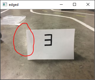
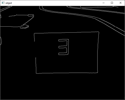
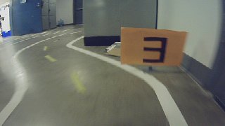
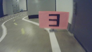
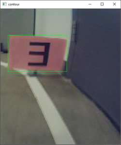
We ended up using neon pink construction paper with numbers drawn in black marker for our signs. This design was optimal as the construction paper was matte and did not have any glare when photos were taken with the webcam. We had tried using other materials like folders and we found that the glare off the surface made it hard for OpenCV to properly recognize contours. Here you can see the original picture with glare on the left circled in red. On the right is the edged copy where you can see the contour for the construction paper is not complete due to the glare.
Additionally, we tried a few different colors of construction paper before settling on pink. The camera has a tendency of adding a blue tint to everything in the picture, so pink stood out the most out of all the colors. Additionally, we 3D printed stands for our signs and used cardboard as a backing so we would be able to freely switch out the color as well as rotate them. Here are pictures captured on the camera of the orange and pink signs.
Electronic Design
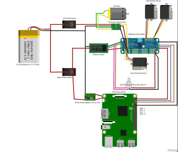
Robocar Wiring Schematic
Software Design
Software Overview
The software can be divided into two parts, which are the motor control and OpenCV number recognition respectively. For the motor control we created our own class called myMotor.py which was added into the parts folder. We based this file off the actuator.py file which already exists as a part in Donkey. myMotor.py contains two classes (myMotor and myMotorThrottle). The myMotor class is in charge of initialization of default values for the motor as well as interfacing with the PWM board (the PCA9685). The myMotorThrottle class contains methods which set the pulse for the motors and thereby controls how fast the motors spin.
Servo Motors
To control the servo motors on top of the car, we used a modified version of actuator.py, which can be found in the default DonkeyCar parts file, since we used the same PWM board to control both the steering and throttle servos as well as the mail delivery servos. Once we created the class, it was simply a matter of adding it as a part to manage.py so the DonkeyCar framework recognized the part.
MyMotor.py takes advantage of the imported Adafruit PCA9685 library for the corresponding PWM board to set the PWM signal. We then manually determined the pulse time constant. The pulse time constant represents how much time it takes to move the slider one box over. For example, moving from box 3 to box 5 would mean spinning the motor for two times the pulse constant and so on. In order to change the default motor speeds, we added the part to the myconfig.py file found in the d3 directory as well as the config variables for the PWM pulses required to stop the motor, spin it clockwise, and spin it counterclockwise.
Neural Network Training
For our neural network training we did not make any changes to the original Donkeycar framework. We used about 12,000 records in order to train a model indoors. One of the main reasons we decided to train our car indoors, was due to the rainy weather outside. The rain not only damaged the signs that we created but also negatively affected our number recognition. This was because there was very low brightness when it rained as opposed to other times when we had trained the model, making it hard for our camera to recognize the proper contours needed for number recognition.
Although the number recognition software operates separately from the Donkeycar framework, it was important to train the model with the signs on the course. If we added the signs after the car had been trained, there was the possibility that the car would not know how to respond when seeing a sign. This is due to the fact that the model associates steering and throttle with a given array of RGB values. we concluded that if we were to introduce a sudden change in the RGB values (i.e. adding a neon pink sign to the course) that the model was accustomed to seeing, our model would not perform as well.
Number Recognition Methodology
Although number recognition can be done in a variety of ways, for our project we decided to use seven-segment number recognition. This process can be broken down into several steps:
1. Color Filtering
In order to create a region of interest within all photos taken by the camera on the car, we decided to make the sign neon pink. Therefore, the first action that we wanted the number recognition software to accomplish was recognizing cropping the photo to only look at the pink construction paper where the number was written. In order to do this, we created a mask using RGB filtering to filter out all colors except for pink. We also know that the sign will be on the right side of the screen so we automatically crop the photo to the right half. Here is a picture of the original input to our camera and the black and white mask we created after color filtering. White represents all pink within the photo and black represents every other color.


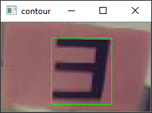
2. Contour Recognition
OpenCV defines a contour as any continuous line of the same color. For our software, there are two contours which need to be recognized. The first contour we call the display contour. This contour is the outline of the construction paper and is easily recognized within OpenCV after the color filtering has been applied. After cropping the photo to only the display contour, we need to recognize the digit contour. This is the contour formed by the digit drawn on the piece of construction paper. The photo is cropped for a final time after the digit contour is found. Two photos of both contours:
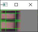
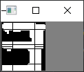
3. Seven Segement Recognition
After isolating the digit contour. The program splits the photo into seven different segments. It then compares how much of each segment is filled with white pixels. If over 50% of a segment is filled with white pixels, then the segment is considered to be present. After repeating this process, a lookup is performed on a dictionary which has digit values associated with each unique seven segment key.
Number Recognition Code
The code first defines a a dictionary for all 10 digits and the corresponding segements which light up in a seven segment display. Each 1, within the DIGITS_LOOKUP represents a lit up segement on a seven segment display.
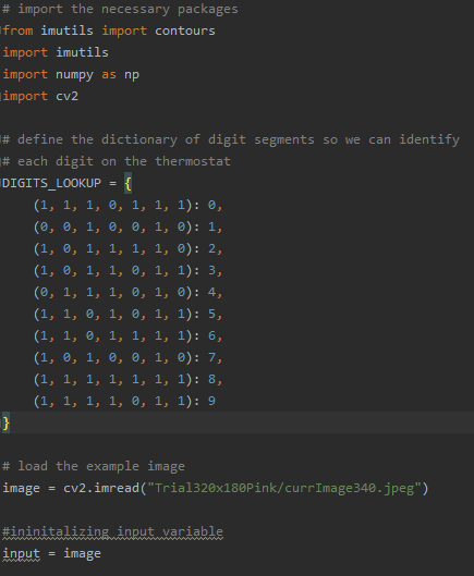
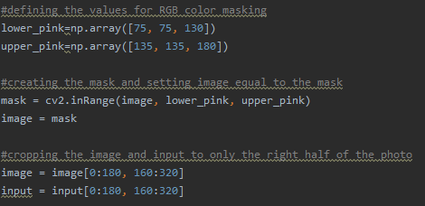
Next, the code defines the upper and lower bounds for the RGB mask, applies the mask to the photo, and then crops the photo to only the right half.
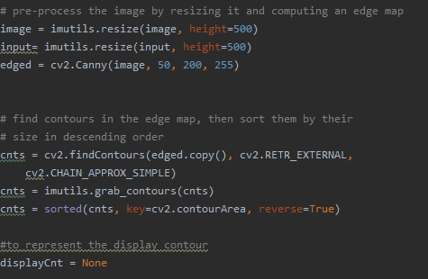
The image is resized and an edge map is created. The program finds all contours within the edge map and then sorts them.
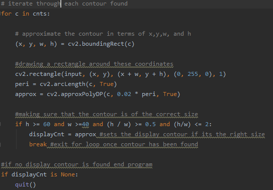
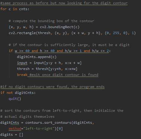
The program iterates through each contour and stops once it has found a contour of the right size. This contour becomes the display contour which represents the piece of pink construction paper.
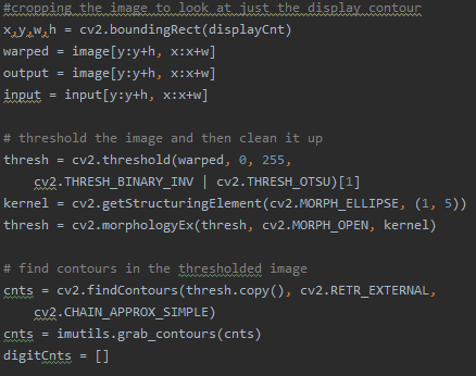
The image is then cropped to just the display contour and a series of operations are applied in order to clean up the photo. This reduces noise and makes it easier to recognize the digit contour. The same process of looking for contours in then repeated to find the digit contour.
This is the second for loop which looks for the digit contour. Once a contour of the appropriate size is found, the image is again cropped to only the digit contour.
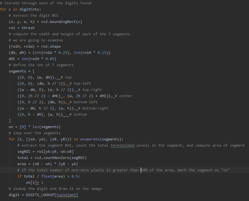
The seven segments are defined and for the digit contour and the program counts the number of pixels within each segment that are nonzero. If the number of "on" pixels in a given segment is greater than 50% of total pixels in the segment, then this segment is considered on. After all segments have been analyzed, a lookup is performed within the dictionary for the number which has these corresponding segments.
Switching between Delivering Mail and Driving Autonomously
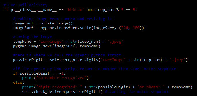
For our project, we decided to not incorporate the mail delivery mechanism as part of the training. We felt that adding extra inputs to the model (servos A and B on top of the car), would introduce too many variables and make it harder for the car to properly drive itself. As a result, the OpenCV script is solely used for number recognition and the Donkeycar framework is only used for autonomous driving. This creates an easy division of labor and allows us to test each piece of software individually in order to verify that it accomplishes its job. However, these two pieces of software cannot operate completely separate as they must work together on the same car. Therefore, in order to integrate the two different pieces of software, we incorporated the OpenCV script into the update_parts method within Donkeycar. Each time update_parts runs, a photo is taken and ran through the OpenCV script. If no number is recognized, the car continues driving. However, if the script recognizes a number, then the throttle for the car is set to zero and the motor sequence is started. After the motor sequence finishes, the throttle is reset and the car can continue driving autonomously. Additionally, we implemented a previous digit instance variable which prevents the car from continually recognizing the same digit while it is stopped. If the digit recognized is the same as the previous digit, then the car continues to run. In this way, the car is always trying to drive itself and the throttle is simply cut if an appropriate number is recognized.
Lessons Learned
Useful Knowledge
Here is a list of things we learned over the course of this project which may be helpful for teams in the future:
1. Native Camera Aspect Ratio
We learned from Team 6 that the native camera aspect ratio is 16:9. They helped us implement code which allows our camera to take photos in its native resolution. This is important as it prevents distortion which can sometimes make it hard to recognize numbers. Especially when objects are in the peripherals of the camera it can be hard to recognize digits as they start to bend excessively.
2. Continuous Rotation vs. Position Servos
It is important to know whether or not your design requires continuous rotation servos or position servos. If position servos are used, then you will be specifying an angle that you want the servos to rotate to. For example, our servos rotated between 120 and 360 degrees. This is opposed to continuous rotation servos where you specify a speed at which they pulse at. We switched back and forth between the two kinds until we finally decided on continuous rotation servos.
3. Weight/Space Management
We designed our parts without taking into consideration size/weight, which ended up overcrowding our robocar. As a result, we had to spend a lot of time reorganizing electronics in order to make sure all of our parts fit properly. Additionally, the increased weight made it so parts of our car sagged and touched the wheels. This was a problem when driving as it made it hard for our car to move and go around turns. In order to fix this, we replaced our current springs with stronger ones. It is important to know how big your components are and plan where they are going to go before buying and testing them on the car.
Challenges and Solutions
This quarter we had a lot of problems with broken parts. We spent a lot of time diagnosing which electronic components were faulty and waiting for new parts. Some of the issues we faced with the electronic parts were
Problem: Robocar would stop randomly during outdoor training
Issue: The on/off switch was very susceptible to vibrations that only occurred when driving outside. These vibrations briefly interrupted power to the Jetson causing it to turn off. We fixed this by replacing the manual switch for the Jetson.
Problem: Couldn't ssh to the Jetson
Issue: Our wifi adapter installed in the beginning of the quarter failed, we had to revert back to the wifi usb to connect to the Jetson. This significantly slowed our workflow for the remainder of the quarter because the slow network connection resulted in slow file transfer. It was also frustratingly laggy to edit files over ssh.
Problem: Jetson Nano 3.3V line broken
Issue: We accidentally connected the 3.3V from the Jetson to V+ instead of VCC on the PWM board. As a result, this created a short and drew too much current from the Jetson into the PWM board. While the PWM board is fine, our wires melted and the 3.3V line no longer is able to produce the correct voltage from any of the pins on the Jetson. We solved this problem by using the 5V output pin on the Jetson. Since the PWM board is rated from 2.3V to 5.5V, we haven't experienced any problems with powering it after switching from 3.3V to 5V.
Problem: Power Converter
Issue: Our DC-DC converter broke and wasn't scaling down the voltage coming in from the LiPo battery. The broken converter only scaled-down the voltage from 12V to 6V instead of 12V to 5V. Since there is overvoltage protection on the Jetson, our Jetson refused to turn on when receiving 6V. We solved this issue by replacing the power converter.
The Final Prototype
Results
We were able to achieve all of our deliverables of circling the track autonomously and delivering specific mail to different locations, in this case the package corresponding to the number on the sign. To achieve this, we successfully implemented number recognition using OpenCV into the donkeycar framework that would trigger the mail delivery sequence when a number is detected. We also successfully interfaced the continuous rotation servos with the PCA 9685 PWM board and integrated the part into the donkeycar framework so we could control it using the Jetson Nano. On testing, we also confirmed that we could move the location of the signs around the track and the car would still stop at each one to deliver the package. In full autonomous mode, we confirmed that the car could resume driving after delivering a package.
We implemented one of our nice to haves, letting the user choose which package gets delivered to which driveway.
Mail Delivery In Action
While driving autonomously (local angle mode), the car is able to do laps around the track and stop at the signs to deliver the 3D printed packages. The car delivers the third package to the sign labeled three and the fourth package to the sign with the four. After delivering the package, the car is able to resume driving around the track.
The package delivery also works in full autonomous mode.
Future Improvements/Ideas
We could improve our DonkeyCar by improving the precision of the mail delivery and the robustness and accuracy of the number recognition system.
Primarily, there are many changes we could make to the package delivery system. Some ideas include:
- Implementing a control system with limit switches as end stops. We could then replace hard coded values such as the pulse time constant with a more robust system that can respond to any environmental factors that affect the speed of the pinion.
- Decrease the weight of the mechanical components.
- Add an additional driving routine that aligns the car with a driveway or a mailbox before pushing off the package.
- Replace the pushing rack and pinion mechanism with a pick and place mechanical arm to more precisely place package at delivery location as well as deliver packages more delicately.
- Use TOF sensors in order to be more precise when aligning the car with the driveway and for distance measurement.
We could also increase the robustness of the number recognition system:
- Take advantage of the GPU's on the Nvidia Jetson to implement a neural net to recognize numbers. (say how this improves model here)
- Our current system requires us to drive relatively slowly to ensure that we don't miss the number signs in between camera captures.
- Test in different environments with different lighting.
- Each environment requires specific calibration in regards to lighting. If we were able to create multiple masks which screened for different RGB values depending on lighting, it would make our number recognition more accurate.
References
This is the starter code for the OpenCV number recognition we used: https://www.pyimagesearch.com/2017/02/13/recognizing-digits-with-opencv-and-python/ Donkeycar documentation: http://docs.donkeycar.com